
Today’s rising temperatures put added stress on HVAC systems. One key component to a balanced system and healthy building envelope is in airflow measurement. Airflow readings are used to measure supply, return, exhaust, or spill air, as well as outdoor air. These can be used to control the HVAC systems to maintain space pressure and temperature relationships to maximize the system performance, minimize energy consumption and maintain a safe environment. This is particularly important in critical spaces such as pharmaceutical, laboratory and healthcare applications.
The purpose of this article is to discuss the three most common technologies used for measuring airflow and how they are applied. Measuring airflow in ductwork is more difficult than measuring flow in pipes it’s typically easier in pipes to get the necessary “straight run” required to get a good measurement location.
Ductwork tends to be larger, operating at lower pressure and usually has many turns or bends. Airflow in ductwork at low pressure can be distorted or compressed, creating flow profile distortion, which must be taken into consideration when positioning an airflow measurement device.
Airflow devices can also be utilized in fan inlets where the airpath is better defined. Depending on the technology used, system effect needs to be considered to avoid any fan performance issues.
Airflow Measurement Technologies
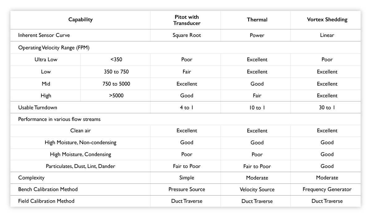
The three predominant technologies commonly used for continuous airflow measurement in fan inlets and ductwork are differential pressure, thermal anemometers and vortex shedding.
Differential Pressure Transmitter
With differential pressure (Figure 1), a pitot tube measures total pressure and static pressure to determine the velocity pressure from which air velocity can be derived. The pitot tube is inserted into the duct with the tip or ports pointed toward the airflow. The positive port of the manometer is connected to the total pressure port, and the negative to the static pressure port.
In larger ductwork, arrays or multiple tubes are used to get a velocity average. These are connected to the differential pressure transmitter that gives a velocity pressure, which can be converted to velocity through a square root calculation. Also, note that each pitot station has a K factor that is particular to the device.
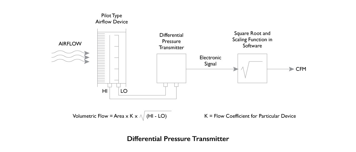
Figure 1
Thermal Anemometer
A thermal anemometer (Figure 2) is made up of two sensors: an air velocity sensor and a temperature compensation sensor. The velocity sensor is heated to an elevated temperature (relative to the surrounding air) by means of controlled electronics. The temperature compensation sensor senses the ambient (surrounding) air temperature and forces the velocity sensor to stay at a constant “overheat” above the ambient.
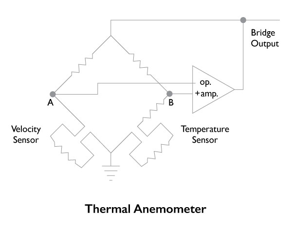 Figure 2
The sensors form two opposite lags of a Wheatstone bridge. The circuit forces the voltage at point A&B to be equal by means of an operational amplifier. Airflow beyond the velocity sensor tends to cool the sensor, thus driving down its resistance.
The operational amplifier responds by delivering more power to the top of the bridge to maintain voltage equilibrium at points A and B. As more air flows past the sensor, more power is required to maintain a balanced bridge. The power going into the top of the bridge is related to the velocity of the airflow past the sensor.
The amount of current required to hold the differential temperature is measured and used in a formula utilizing King’s law to determine the velocity. The electronics will then average the point velocities to determine the average velocity through the duct, calculating total airflow.
Vortex Shedding
Vortex shedding devices use an array of individual sensors arranged across the ductwork to sense velocities. Each sensor includes a trapezoidal shedder element or bluff body (Figure 3), which creates eddy currents or vortices as the air moves over it. These eddies alternate from side to side, creating pressure pulses that are directly proportional to the velocity of the air. Transducers (small microphones) sense the pressure fluctuation frequency, and electronics average the sensors and output a linear flow signal.
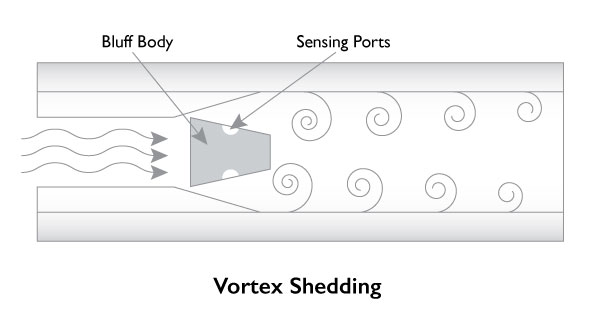
Figure 3
Vortex shedding is a frequency-based digital device, not amplitude-based. The sensing technology is not analog, nor is it affected by zero drift or hysteresis concerns that are associated with pitot tube pressure transmitters. And, because vortex sensing technology does not drift over time, no recalibration of the electronics is required.
The other airflow technologies discussed in this article rely on an amplitude measurement device, which is susceptible to inaccuracies and drift. Pitot and orifice sensors rely on differential pressure transmitters, which require periodic calibration. Thermal airflow sensors use thermistors, which can drift over time. The environmental conditions also need to be considered, as the sensing devices could be susceptible to clogging.
Basic Operation and Application Capabilities
Device Location
Airflow measurement devices are affected by duct conditions up and downstream of the device. Most commercially available devices are designed to handle the twists and turns in the ductwork. Extreme cases create turbulence, which degrades the performance (accuracy) of these devices.
Each manufacturer offers suggestions for mounting limitations in their Minimum Installation Requirements Guide (Figure 4). However, these should be taken as worst-case guidance only.
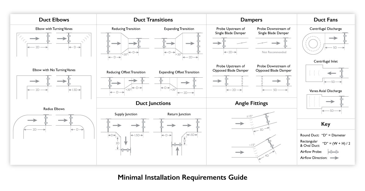
Figure 4
The designer must realize that the recommendations typically show only one duct disturbance-producing mechanism located either up or downstream of the device and only in one plane. The reality is that in typical ducting systems, there are multiple disturbance-producing mechanisms that exist both before and after the device and in three planes. It is essential that the designer keeps this in mind to achieve the best possible locations based on the specific space constraints and not just focus on achieving minimums.
In addition, it is important to avoid locations where air is decompressing, such as the discharge of a fan, elbows, and after expanding transitions. One of the most common errors is locating the airflow sensor is after a control damper instead of before. By locating the airflow sensor before the control damper, airflow turbulence is reduced dramatically.
It is common for contractors to change locations and sizes to minimize fabrication costs. Therefore, these locations should be reviewed again when sheet metal shop drawings are completed.
Summary
If it’s important, you should measure it. Knowing what an HVAC system is doing and being able to adjust to optimize performance is key to improving a building’s overall health and energy footprint. Incorporating properly selected, sized and installed airflow measurement control equipment is a key component to achieve these goals.
For further information about aiflow measurement technologies for your HVAC system, please call us at 203-261-8100 or email us.


